YSSC2P is a PCI interface adapter compatible with Mitsubishi MR-J2S-B SSCNET II network servo amplifiers. It supports up up to six MR-J2S-B drives in position or velocity control mode. The card also features general-purpose I/O headers for connecting to limit switches and relays. The software includes LinuxCNC 2.7 driver module and an optional patch for absolute encoder support.
* SSCNET is a synchronous high-speed network for servo drives and motion controllers. SSCNET only requires a simple daisy chain wiring between servo amplifiers. See Mitsubishi documentation for details.
The card layout showing connectors and indication LEDs:
LEDs
| D1 - servo amplifier status | |
|---|---|
| green | servo amplifiers initialized |
| red | SSCNET receive CRC error |
| D5 - error | ||
|---|---|---|
| red | continuous | FPGA boot error |
| D6 - firmware status | ||
|---|---|---|
| amber | continuous | FPGA boot error |
| amber | long off/short on | firmware is standing by |
| amber | long on/short off | firmware is in sync with LinuxCNC |
| J1 - CN2 power | ||
|---|---|---|
| 1-2 | CN2 pins 18, 20, 22, 24, 26 connected to ground | |
| 2-3 | --//-- to +5V* | |
| J2 - JTAG | |||
|---|---|---|---|
| 1 | TCK | 2 | GND |
| 3 | TDI | 4 | TDO |
| 5 | TMS | 6 | VCC 3.3V |
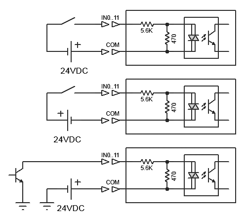
CN1 contains 12 optoisolated digital inputs. External 24VDC field power supply is required for operation. Example connection of open-collector outputs or mechanical switches is shown on schematics.
| CN1 | |||
|---|---|---|---|
| 1 | IN0 | 2 | IN1 |
| 3 | IN2 | 4 | IN3 |
| 5 | IN4 | 6 | IN5 |
| 7 | IN6 | 8 | IN7 |
| 9 | IN8 | 10 | IN9 |
| 11 | IN10 | 12 | IN11 |
| 13 | COM0-7 | 14 | COM8-11 |
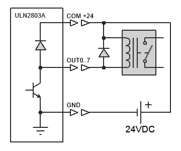
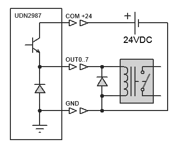
CN3 has 8 open-collector outputs from ULN2803A IC. Each output is rated to 500mA/50V max. Total current should never exceed 2.5A. Pin 9 connects to positive terminal of the field power supply for flyback protection diodes when using inductive load such as magnetic relays.
CAUTION! Relay driver IC has no overcurrent protection. If short-circuited it WILL burn and destroy the FPGA rendering the controller completely unusable. Duoble-check all connections before supplying power.
| CN3 | |||
|---|---|---|---|
| 1 | OUT0 | 2 | OUT1 |
| 3 | OUT2 | 4 | OUT3 |
| 5 | OUT4 | 6 | OUT5 |
| 7 | OUT6 | 8 | OUT7 |
| 9 | COM +24V input | 10 | GND |
CN2 connector is intended for daughter boards with future firmware upgrade. Version 1.0 supports TTL quadrature encoder inputs A, B, Z.
All IN12..IN28 lines are 3.3V LVTTL and are 5V tolerant.
Pins 18, 20, 22, 24, 26 optionally provide 5V power to external devices. The power is taken from the PCI bus and fused to 500mA.
| CN2 | |||
|---|---|---|---|
| 1 | IN28 | 2 | IN27 |
| 3 | IN26 | 4 | IN25 |
| 5 | IN24 | 6 | IN23 |
| 7 | IN22 | 8 | IN21 |
| 9 | IN20 | 10 | GND |
| 11 | IN19 | 12 | GND |
| 13 | IN18 | 14 | GND |
| 15 | IN17 | 16 | GND |
| 17 | IN16 | 18 | GND or +5V |
| 19 | IN15 | 20 | GND or +5V |
| 21 | IN14 | 22 | GND or +5V |
| 23 | IN13 | 24 | GND or +5V |
| 25 | IN12 | 26 | GND or +5V* |
Alternative CN2 pins functions depend on the mux configuration
| CN4 | |||
|---|---|---|---|
| 1 | LG | 11 | LG |
| 2 | RD | 12 | RD* |
| 3 | 13 | ||
| 4 | TD | 14 | TD* |
| 5 | LG | 15 | LG |
| 6 | 16 | ||
| 7 | EMG | 17 | EMG* |
| 8 | 18 | ||
| 9 | 19 | ||
| 10 | 20 | ||