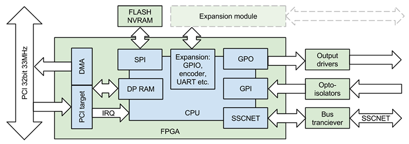
The controller is implemented in a Xilinx Spartan-6 FPGA. It includes a PCI controller core and a system-on-a-chip with a soft-core CPU. The CPU executes a firmware which handles communication with servo drives and I/O processing. The communication with the host computer is handled via a dual-ported RAM and interrupts.
The software executes an endless loop with a 0.88ms period. Below is a timing diagram of a cycle:
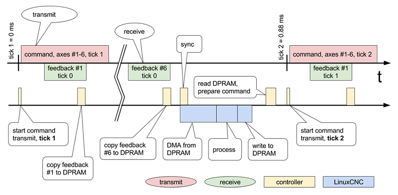
The controller cycle begins with a timer interrupt which starts a transmission of a SSCNET control frame. In response servo amplifiers transmit a feedback frames in sequence defined by their IDs. The controller receives, processes and writes it to the exchange buffer in the DPRAM. After all feedback received the controller waits for a sync interrupt from the host driver. Measuring the timing of the interrupt the controller slightly adjusts its 0.88 timer so that to be in sync with the servo thread of the LinuxCNC.
On each servo thread cycle LinuxCNC calls driver function. At the beginning of execution the drivers generates a sync interrupt to the controller processor. Following that the driver starts the DMA engine to copy feedback data from the dual-port buffer RAM to system RAM with a PCI burst transfer. Received data is used to update HAL output pins of the driver. Then driver HAL input pins are read and values used to compose a command packet for the next cycle which is written to the dual-port RAM buffer.
Then the controller processor receives second timer interrupt on which it reads command packet from DPRAM buffer, and prepares a SSCNET control frame using the data received from the host driver. The cycle repeats.